Table of contents
- 1. Introduction
- 2. Hardware
- 3. Software
- 4. Configuration
- 4.1. ADC Configuration
- 4.2. UART Configuration
- 4.3. Shot duration
- 5. Debugging
- 6. Setup
TOC
- 1. Introduction
- 2. Hardware
- 3. Software
- 4. Configuration
- 4.1. ADC Configuration
- 4.2. UART Configuration
- 4.3. Shot duration
- 5. Debugging
- 6. Setup
Other pages:
Introduction
This wiki presents the system developed for the real-time calculation of the plasma electron density at the ISTTOK tokamak using data from the microwave interferometer (100 GHz). This variable is a fundamental parameter in a fusion plasma and its knowledge is essential for the real-time control of the plasma.
A low cost, embedded system was developed for the real-time calculation. This consists on a board responsible for the signal conditioning, with analog inputs where the interferometer outputs are connected, followed by another board with a dsPIC that digitizes, calculates, detects a discharge at the ISTTOK and sends the results by serial communication through an UART module.
The original goals of this system were a calculation frequency of at least 20 ksps and a transmission rate of 1 kHz. These goals were easily achieved and overcame being the maximum calculation frequency 98.30 ksps and the transmission rate 25 kHz (by RS232).
The system produced results with great quality, very close to those of the offline calculation, in an extremely reliable way.
Hardware
The system consists on two pieces of hardware: a signal conditioning board and the microprocessor board.
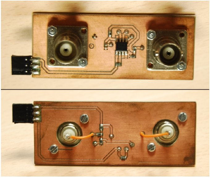
The first is responsible for reducing the voltage range of the interferometer signals into half and creating an offset of 2.5 V. To connect the interferometer analog outputs to the board two BNC connectors are used.

Figure 1: Above - picture of the top view of the signal conditioning board: below - bottom view of the signal conditioning board.
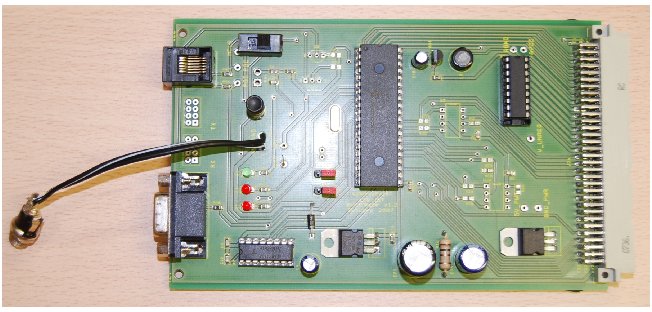
The microprocessor chosen was the dsPIC30F4013 due to its easiness of use, versatility and low-cost. It is inserted in a board responsible for the power supply and I/O's ports.
In terms of speed, the microcontroller uses an external crystal oscillator and a PLL to obtain an instruction frequency of 29.4912 MHz.
The microcontroller possesses two independent UART modules responsible for asynchronous communication in full-duplex. This communication can be made at the standard baud rates 9600, 19200, 38400, 115200 and 460800 by RS232 and also 921600 by optic fibre with practically no error. Due to the low transmission rates necessary for this project, the communication was established by RS232 connecting the D9 port on the board with the serial port of a computer.
Finally, the microcontroller has an ADC module with one 12-bits ADC, with a maximum sampling rate of 200 ksps, 16 analog inputs and a Sample/Hold circuit. Since there are two signals that need to be sampled simultanously, the sampling of the channels is performed in a multiplexed way and a virtual synchronization is performed afterwards. This way, the sampling rate used must be divided by two and a maximum sampling rate of 100 ksps is achieved.

Figure 2: Microprocessor board for the power supply and I/O's ports.
Software
The microprocessor was programmed in C due to its simplicity. Although the C allows the use of many functions to simplify the dsPIC configuration, our approach was closer to assembly by writing directly into the microprocessor registers to maximize the performance of the program, which is essential in a real-time application.
Figure 3, 4, 5 and 6 show flowcharts where the program is described.

Figure 3: Program flowchart. The program begins by configuring the UART and A/D modules. Then the phase offset is calculated as the 8-points average. Each time an acquisition is performed the phase is calculated and compared with the offset. If a discharge is detected, then the program changes to shot state. There, with each acquisition, besides the phase calculation, there is a test to see if the measurements correspond to extremes and the unwrap algorithm is executed. At the programmed frequency the result is transmitted and this cycle is repeated until the discharge is over. When this happens the signals offset are calculated and the program retuns to the beginning.

Figure 4: Acquisition flowchart. After the new data has been converted the sin is stored and multiplied by 16 by 4 left shifts. This is done to increase the resolution of the algorithm for calculating the phase shift. Then the cos is stored and summed with its last value. The result is then divided by 2 by a single right shift, obtaining this way an interpolation of both values.

Figure 5: Phase calculation flowchart. After the acquisition storage the phase is calculated by the method described. If the cos is null, the result is immediately found and the ratio sin/cos is not calculated. Otherwise, the 16 tan is obtained and used as a pointer to a table containing the arctan in the first quadrant. By signal evaluation of the sin and cos variables, the result is extended to the four quadrants.

Figure 6: Unwrap flowchart. To check if an interference fringe has been achieved a simple comparation between two consecutive values is performed. If the difference between the previous result and the current one is higher than pi a positive turn was completed and if the same difference is inferior to -pi a negative turn was verified.
The A/D module is configured by writing in six registers: ADCON1, ADCON2, ADCON3, ADCHS, ADPCFG and ADCSSL where the parameters that control the ADC are filled. Regarding the UART module configuration, the registers are now the UxMode, UxSTA, UxRXREG, UxTXREG and UxBRG. The small caps x can take either 1 or 2 referring to both UART modules. In this project only the UART2 was used, since it is the one which is connected to the D9 connector to the board. If communication by optic fibre is to be used then the UART1 should be chosen (if the same microprocessor board is used).
Configuration
The first step of the microprocessor configuration is configuring the Configuration Bits in the Configure tab in the MPLAB IDE. The "Configuration Bitsset in code" should be left disabled, the Oscillator should be set in XT w/PLL 16x and Watchdog Timer should be disabled. These are the only changes to the default settings.
In the code several parameters can be configured.
ADC Configuration
The register ADCON3 contains all the information regarding the sampling time and the configuration time. The conversion time is 14 ADC clock cycles (TAD) - 12 cycles for each bit and one more before and after the acquisition. The sampling time can be defined by the programmer in multiples of TAD with 1 TAD being the minimum.The ADC clock cycle is defined as a multiple of the microcontroller instruction cycle (TCY). Therefore, in order to specify the sampling frequency, it is just necessary to configure these two parameters: the number of TAD for the sampling time and the duration of the TAD itself. It is possible to have the same sampling rate with different configurations.
The parameter SAMC<4:0> = ADCON3<12:8> should be written with the number of TAD in the sampling time. Besides this, the parameter ADCS<5:0> = ADCON3<5:0> determines the number duration of one ADC clock cycle according to:
TAD = TCY (ADCS + 1) / 2
The rest of the bits of ADCON3 should be left at zero.
For example, a configuration that was studied and produced very good results was seting the TAD as 15 times TCY (ADCS = 0d29 = 0b11101) and the sample time of just one TAD (SAMC = 1). This way the register ADCON3 should be written with 0x011D. This configuration corresponds to a sampling rate of 65.56 ksps.
UART Configuration
The register U2BRG is responsible for the choice of the baud rate used in data transmission and its value should be calculated according to:
U2BRG = FCY/(16*BaudRate)- 1
where FCY is the instruction frequency (1/TCY)
To use the standard baud rates, the folowing correspondance can be taken into account:
| Baud Rate | U2BRG |
| 9600 | 191 |
| 19200 | 95 |
| 38400 | 47 |
| 115200 | 15 |
| 460800 | 3 |
| 921600 | 1 |
The UART was configured to send data in the 8-bit format with no parity and just one stop bit. Other configurations can be set (for more information see the dsPIC30F Family Reference Manual).
When a discharge is detected the program sends the shot number through the UART module. After that the results start being sent at the programmed rate. Since the phase is coded as a 16-bit integer, the result is split into two 8-bit words. First the most significant bits are sent and then the others.
To set the transmission rate the constant DIVISOR must be defined. This value determines the number of times a result is determined for each transmission. In other words, the transmission rate will be the calculation rate divided by the DIVISOR.
Shot duration
Since the program is not able to determine automatically the end of one discharge, the programmer should define the constant SAMPLES with the number of samples to be made during each shot. This value should take into account the sampling frequency configured.
Debugging
For debugging two pins can be switch on and off in order to measure the time of execution between two lines of code. To do this it is just necessary to put 1 or 0 into LATbits.LATB3 or LATbits.LATB2. In the code this is already written as a comment in some important places.
Setup
After properly configured, the system is ready to operate. For this, the interferometer outputs should be connected to the signal conditioning board. The sin signal should connect to the left connector on the board and the cos to the right one.
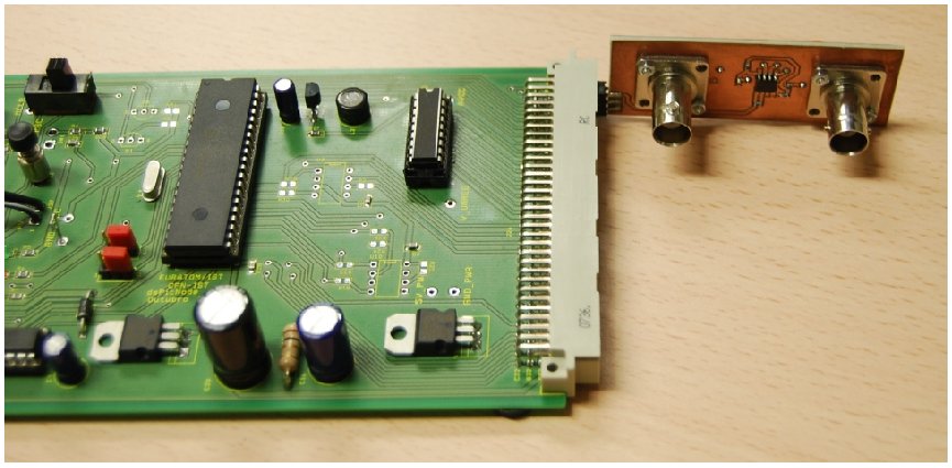
The signal conditioning board should then connect to the microprocessor board as it is shown in figure 7.

Figure 7: Signal conditioning board connected to the microprocessor board.
The connections should be made in the second and third pin (leave one pin open in the end).
After everything is connected the microprocessor board should be turned on. If the board was already on, it should be reset. The system is now ready to detect a discharge and start transmitting the results by RS232.
- Was this page helpful?
- Tag page (Edit tags)
- What links here
Files 10
| File | Size | Date | Attached by | |||
|---|---|---|---|---|---|---|
| dissertation.pdf Full master thesis | 8.48 MB | 18:12, 10 Feb 2011 | Admin | Actions | ||
| extended_abstract.pdf Full master thesis | 3.08 MB | 18:12, 10 Feb 2011 | Admin | Actions | ||
| Figure-0.jpg Full master thesis | 67.78 kB | 18:12, 10 Feb 2011 | Admin | Actions | ||
| Figure-1.jpg Full master thesis | 57.21 kB | 18:12, 10 Feb 2011 | Admin | Actions | ||
| Figure-2.png Full master thesis | 96.9 kB | 18:12, 10 Feb 2011 | Admin | Actions | ||
| Figure-3.png Full master thesis | 23.14 kB | 18:12, 10 Feb 2011 | Admin | Actions | ||
| Figure-4.png Full master thesis | 68.66 kB | 18:12, 10 Feb 2011 | Admin | Actions | ||
| Figure-5.png Full master thesis | 32.65 kB | 18:12, 10 Feb 2011 | Admin | Actions | ||
| Figure-6.jpg Full master thesis | 70.61 kB | 18:12, 10 Feb 2011 | Admin | Actions | ||
| RealTimeDensity.zip Full master thesis | 66.07 kB | 18:12, 10 Feb 2011 | Admin | Actions | ||
| Images 7 | ||
|---|---|---|
 Full master thesisFigure-0.jpg |  Full master thesisFigure-1.jpg |  Full master thesisFigure-2.png |
 Full master thesisFigure-3.png |  Full master thesisFigure-4.png |  Full master thesisFigure-5.png |
 Full master thesisFigure-6.jpg | ||
